Fiber Optic Loss: Causes, Measurement & Prevention
In professional telecommunications infrastructure, performance is defined by measurable results. One of the most critical parameters influencing network reliability and long-term stability is fiber optic loss, also known as attenuation. Optical loss represents the reduction of signal power as light travels through the fiber and is typically expressed in decibels (dB) or decibels per kilometer (dB/km). If not properly controlled, excessive attenuation can limit transmission distance, reduce signal quality, and increase the need for active equipment or amplification.
Fiber optic loss originates from several key factors. Intrinsic attenuation is inherent to the fiber material itself and includes absorption and scattering within the glass core. Modern single-mode fibers are engineered to minimize this effect, particularly at standard operating wavelengths such as 1310 nm and 1550 nm. Bending losses are another common cause. Macro-bending occurs when the cable is curved beyond its recommended radius, allowing light to escape the core, while micro-bending results from small deformations or mechanical pressure on the fiber. Both can significantly increase attenuation if installation standards are not respected.
Splice loss is introduced when fiber ends are not precisely aligned during fusion splicing or when contamination affects the joint. Even minor misalignment can lead to measurable signal reduction. Connector loss is also a frequent contributor to performance degradation. Dust, improper polishing, or low-quality connectors can increase insertion loss and negatively affect overall link performance. In addition, return loss caused by back reflection can impact system stability, particularly in high-speed or long-distance transmission environments.
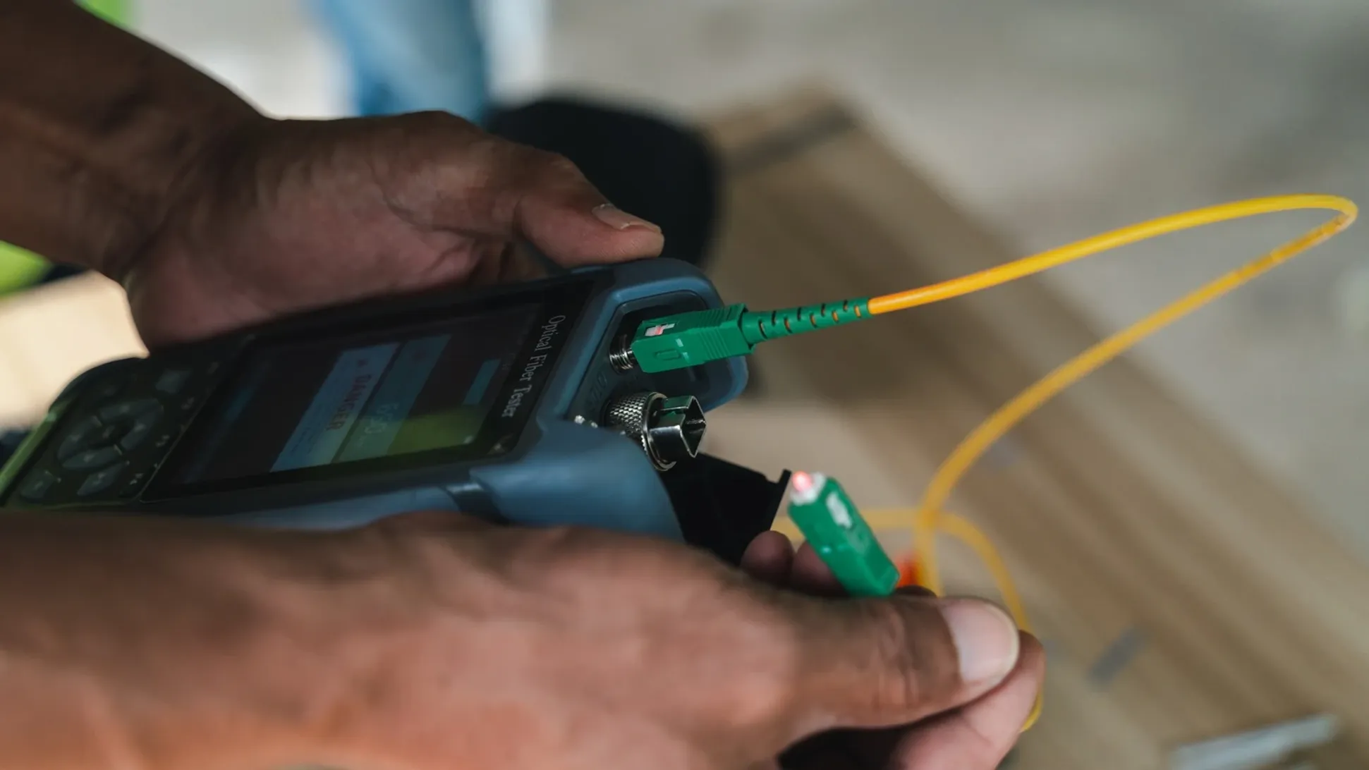
Accurate measurement is essential to ensure that a fiber link meets design and performance specifications. Insertion loss testing, performed using a calibrated light source and power meter, measures total attenuation across a link and is commonly used for certification and acceptance. Optical Time Domain Reflectometer (OTDR) testing provides a more detailed analysis by identifying splice points, connector losses, bends, and faults along the cable length. Together, these testing methods provide a comprehensive understanding of network integrity.
Preventing optical loss begins at the design stage and continues through installation and maintenance. Selecting the appropriate fiber type for the required distance and bandwidth, maintaining proper bend radius during routing, using certified splicing equipment, cleaning connectors before every connection, and performing systematic testing are fundamental practices. Fiber performance is not determined by a single component but by the integration of cable quality, installation discipline, validation processes, and long-term maintenance strategy.
Managing fiber optic loss is not only about meeting initial project specifications; it directly influences scalability, upgrade capability, and operational efficiency. Low-loss infrastructure ensures greater flexibility for future expansion and supports higher data rates as network demands evolve. In professional telecommunications environments, optical performance is not assumed — it is engineered, measured, and continuously verified.